Category Archives: Hardware

A makeblock 3d printer chassis

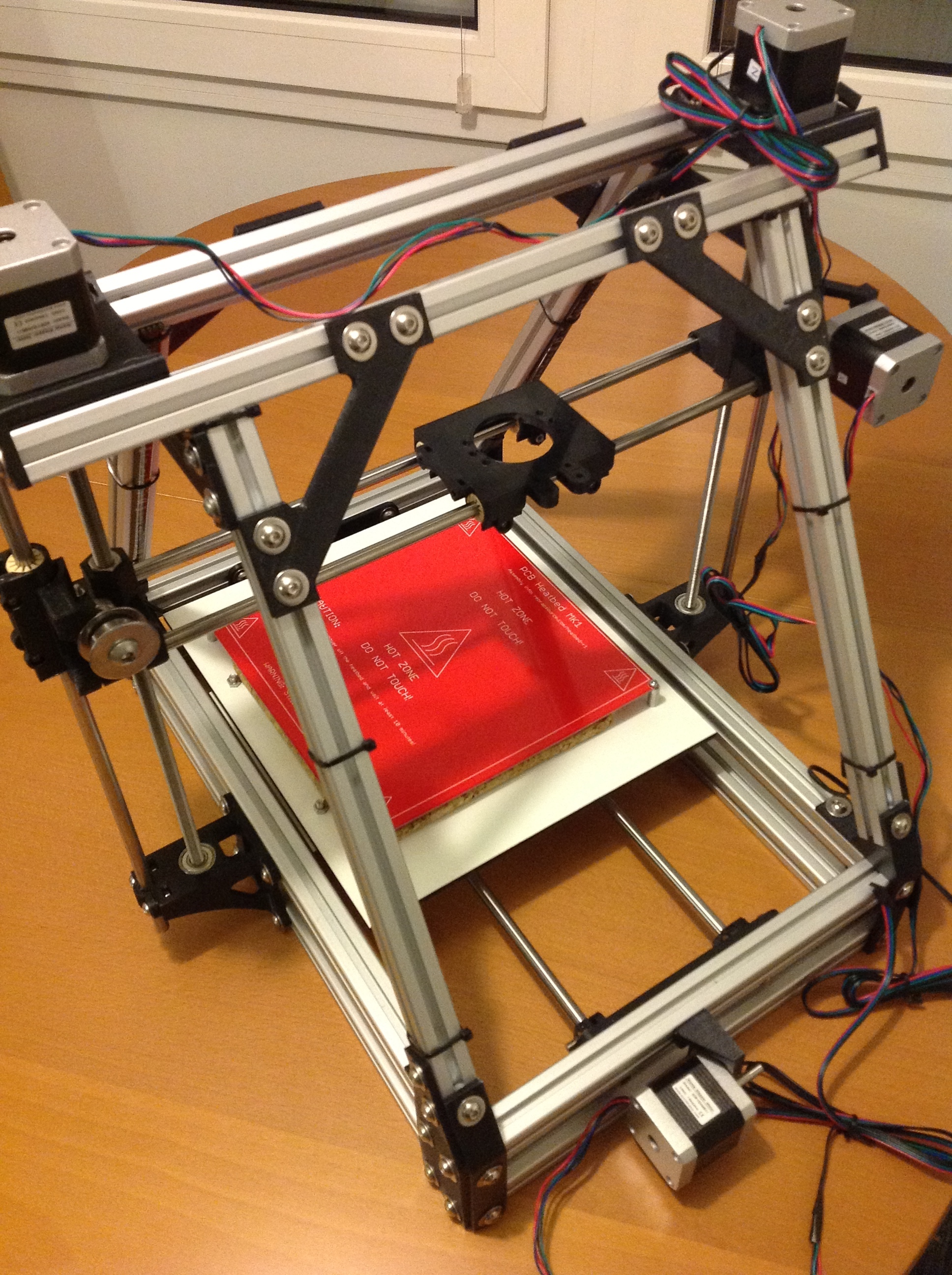
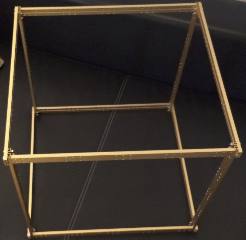
My Mendelmax 3d printer has come to age and I’m not anymore satisfied with the format and design, so when I found some 50% discount on makeblock parts at my favourite tech store EXP Tech, I decided to start a new 3d printer design from ground up using makeblock components.

IMG_0476

I’m not yet sure which basic hardware principle the 3d printer will finally have (CoreXY vs traditional 3 axes, but definitely not a delta system), using v rail sliders vs linear motion guides or traditional round motion shafts.

I bought so many makeblock parts that I might be able to test out any of these concepts.

IMG_3226

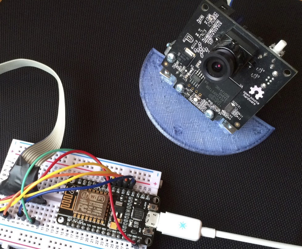
Further I was able to get a milling spindle and a capacitive distance sensor, and maybe I’ll add a laser engraving option later on.

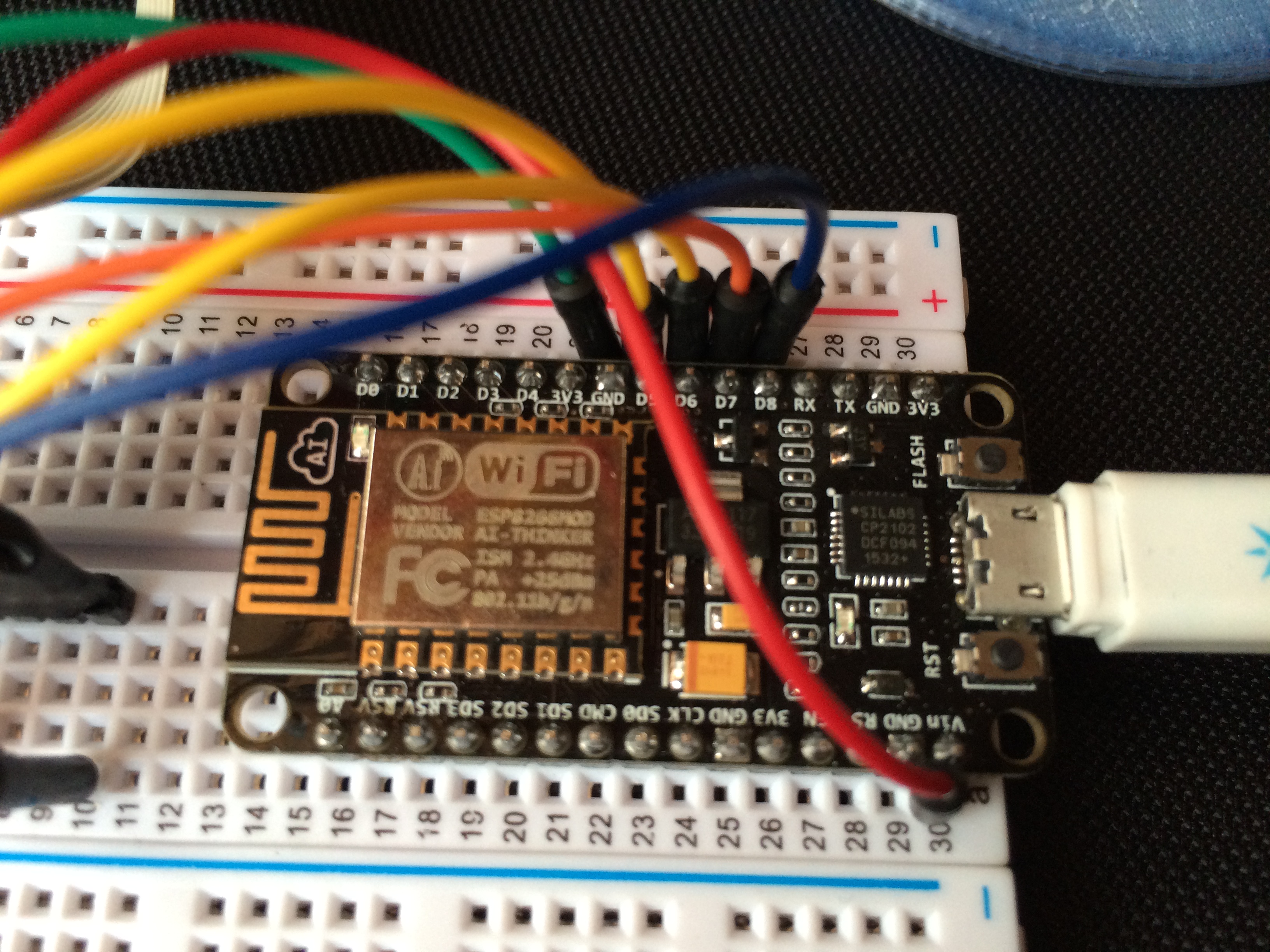
Also replacing the electronics RAMPS and arduino with more capable stepper drivers and 32bit microcontroller with floating point support might change the way my old Mendelmax used to print things, allowing bigger speeds and more smooth and exact positioning than before.

We will see, lots of stuff to try out in my holiday.

Connecting the Pixycam via NodeMCU WiFi

Finally, whenever I tried to connect my 4 Pixycam for realtime coloured object tracking for the Teddy Robot, I experienced trouble wheter connecting them via USB (saturating the USB Host adapter bandwidth, or colliding due to a previously non-existing Pixycam Device enumeration), connecting them via serial or I2C to my micropython boards (bandwidth problem, not enough serial lines for 4 cameras), connecting them via SPI (previously no slave selection support on pixies).

IMG_3224

Now with the NodeMCU board and SPI SS support in the latest Pixycam firmware, I managed to run the color object tracking code on only one microcontroller querying 4 cameras via SPI on one bus in full speed and even transmitting all the block data via Wifi to a websocket server.

With slower arduino or even maple or micropython STM32 boards this would have never been possible.

The websocket server has a low enough latency of 2ms, which is great via WiFi. When trying to relay the same data via MQTT I got a lot of stack traces again. One day I need to directly embed ROSserial via WiFi to see if the websocket translation into ROS can be omitted.

Experimenting with the ESP8266 NodeMCU

Another microcontroller finally found its way into my hands.

The ESP8266 based NodeMCU is running at 80Mhz (or even 160MHz) and has WiFi built in for a ridiculous pricetag of only 10 Euro.

IMG_3225

Initially they come with an embedded LUA interpreter preinstalled, to allow some easy scripting of event based code rather than writing and compiling C code. As LUA is not completly reentrant after Wifi events and also consumes a lot of processing power, my projects will be further written in C, so I evacuated the LUA bootloader.

Compared to Spark Cores and their always connected to the cloud behaviour, they can be configured within the standard Arduini IDE (using the ESP8266 plugin). Code can even be flashed over the air and/or served from a webserver. And if neccessary they can provide an Accesspoint of their own.

Some drawbacks that I’ve already found is that Wifi disconnects when using the only analog pin on the board, and I’ve seen lots of stack traces and crashs whenever the Wifi background timing gets disturbed to much by local code. Otherwise for short codepaths the NodeMCU can instantaneously turn every small arduino project into a more capable Internet of Things project, without much effort and/or changing of lots of code.

I’m even thinking about replacing my 5 Spark Cores which are monitoring temperature, humidity, windows, doors, light and motion at my home. Only the analog thing loosing Wifi connectivity is a showstopper for me.

For more digital projects and lots of serial communication, this is the way for me to go, so I am ordering another 2 NodeMCUs.

Finally got GPS working on the Cubieboard

Sometimes the solution would be easy….

…damn I swapped Rx and Tx and everything went fine,
and I was so sure I connected, documented and even checked multiple times that all is as it should.

At first I thought the level shifter isn’t working, but my brand new Open Workbench Logic Sniffer showed signals, same signals before and after shifting, and was even able to autobaudrate guess my GPS defaults which is 38400.

As I 3D printed a case for the cubieboard I needed to remove the board from the robot anyway so I had the chance to look at the tiny pin headers again, oh and yes I swapped the cables for Rx and Tx there…. damn.

Configuring ROS Dynamixel controllers

Installed the ROS hydro components for the dynamixel servos, and configured the pan tilt controllers.

Software so far looks OK, now I need to re-vive the dynamixels from the arduino and hopefully the protocol CRC errors will be gone.


<launch>
<node name=”dynamixel_manager” pkg=”dynamixel_controllers” type=”controller_manager.py” required=”true” output=”screen”>
<rosparam>
namespace: dxl_manager
serial_ports:
pan_tilt_port:
port_name: “/dev/ttyACM0″
baud_rate: 57600
min_motor_id: 1
max_motor_id: 13
update_rate: 20
</rosparam>
</node>
</launch>


<launch>
<!– Load controller configuration to parameter server –>
<rosparam file=”$(find teddy_dynamixel)/config/dynamixel_joint_controllers.yaml” command=”load”/>

<!– start specified joint controllers –>
<node name=”dynamixel_controller_spawner” pkg=”dynamixel_controllers” type=”controller_spawner.py”
args=”–manager=dxl_manager
–port=pan_tilt_port
–type=simple
pan_controller
tilt_controller”
output=”screen”/>
</launch>


pan_controller:
controller:
package: dynamixel_controllers
module: joint_position_controller
type: JointPositionController
joint_name: pan_joint
joint_speed: 2.0
motor:
id: 11
init: 512
min: 0
max: 1023

tilt_controller:
controller:
package: dynamixel_controllers
module: joint_position_controller
type: JointPositionController
joint_name: tilt_joint
joint_speed: 2.0
motor:
id: 12
init: 512
min: 0
max: 1023

Move to ROS hydro supplied GSCAM

Meanwhile ROS hydro has it’s own gscam modules released, so I migrated from my own compiled module and also reconfigured the topic remapping.


ptzcam.launch file:

<?xml version=”1″ encoding=”utf-8″?>
<launch>
<node pkg=”gscam” type=”gscam” name=”gscamptz” cwd=”node” respawn=”true”>
<env name=”GSCAM_CONFIG” value=”v4l2src device=/dev/video0 always-copy=false ! video/x-raw-yuv,width=320,height=240,framerate=15/1 ! ffmpegcolorspace”/>
<remap from=”camera/image_raw” to=”/camera/ptz/image_raw” />
<remap from=”camera/camera_info” to=”/camera/ptz/camera_info” />
</node>
</launch>


Teddy Robot process monitoring


Devices:
pyongyang
connected
cubie
connected
arduino1
connected
arduino2
not connected
maple
connected
ROS Processes
ROS Core
running
ROS Serial
running
IMU/AHRS
running
GPS/Client
not running
fix:true
EKF Pose Odometry Fusion
running
Stereo Cameras
running
Stereo Depth Fusion
running
Streamingserver
running
OpenTLD Tracking
not running
Face/Object Recognizer
not running
Speech Recog
not running
Speech Synthesis
not running
SMACH
not running
state:menu
Web Interface
running
Peripherals:
Camera left
connected
Camera right
connected
IMU/I2C
connected
GPS/Serial
not connected
Sonar Front
not yet
dist:40
Sonar Left
not yet
dist:40
Sonar Right
not yet
dist:40
Sonar Back
not yet
dist:40
Pan Servo
not yet
pos:512
Tilt Servo
not yet
pos:512
Nose LED
not yet
color:green
Motor Controller
not connected
USB-Audio
connected
Main Audio Input
not yet
MEMS mic middle
Main Speakers
not yet
vol:50
Camera left mic
not yet
val:25
Camera right mic
not yet
val:25
MEMS mic left
not yet
val:25
MEMS mic right
not yet
val:25
MEMS mic middle
not yet
val:25
CMU front
not yet
objs:0
CMU rear
not yet
objs:0
HW Monitoring
Cubie CPU Speed
768 MHz
PyongYang CPU0 Speed
774 Mhz
PyongYang CPU1 Speed
1800 Mhz
PyongYang CPU2 Speed
774 Mhz
PyongYang CPU3 Speed
774 Mhz
PyongYang CPU0 Temp
74°C
PyongYang CPU1 Temp
70°C
PyongYang Chassis Temp
27.8°C
Maple Temp
not yet
Pan Servo Temp
not yet
Tilt Servo Temp
not yet
Pan Servo Voltage
not yet
Tilt Servo Voltage
not yet
Motor Controller Voltage 12.1V
Motor Controller Currents  0A 0A
Main Voltage 12.8V
Main Amperes  2.4A
Main Watts 30.7W
Disk Cubie
65% free
Disk PyongYang
79% free
Memory Cubie
50% free
Memory PyongYang
59% free